Object related tools
Object related toolsPermalink
![]()
1D Array (Clone Between)Permalink
Set subdivision marks between two points, and place a clone on each mark
- Pick distance start point.
- Pick distance second point.
- Move the mouse towards the start or end point to set segments amount.
- Press SHIFT while tracking second point for orthogonal mode.
- Pick the object to clone when prompted.
Note: Orthogonal tracking (SHIFT) has a axis-lock feature: Keep SHIFT pressed, and having vertex snap activated, move the cursor to a vertex and press CTRL, the tracking will be restricted to the nearest axis, and then you can track any point, the line will lock to that specific axis. This feature works in all the tools that has a orthogonal tracking feature. Alternate mode: Press SHIFT when activating the tool to place the clones at segments midpoint.
![]()
Interactive 2D ArrayPermalink
Quickly create a 2.5D Array of objects, picking points in the viewport.
- Select the object to clone.
- A rectangular area to operate will be delimited:
- Base point
- Second point will determine the height and alignment of the rectangle. Press SHIFT for orthogonal tracking.
- Third and last point sets the width. Keep pressed SHIFT to invert the up-direction
- Move the mouse away from the last point to select the amount of rows. Press left click to finish selecting rows.
- move the mouse again to define columns quantity. press click to finish.
![]()
Pattern ArrayPermalink
Make complex rule-based object arrays; walls, mosaic patterns…
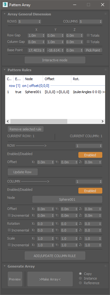
- Array Dimension
- Rows and Columns: Set the amount of rows and columns for the array. Array dimension will be nRows x nColumns. (nColumns per row).
- Checking “Totals” for Rows and Columns separation will use the XYZ values as total distance for rows or columns extension.
- Interactive mode allows to set the array dimension parameters in an interactive way, from the viewport.
- Add rules
- Set a row number in the spinner to add rules to. Press “update Row” if you change the offset parameters for the current selected row number. unchecking “Enable” will turn off the current row, but it’s still used for calculations.
- Set current column for the row. Each added rule will “fill” a cell in the row. 2.1 Pick the node to use. 2.2 Set offset, rotation and scale values. un-checking “Enabled” will left a “hole” in the array, without breaking the rules.
- Once you finish to set the new column, or update the current selected row, press “ADD/UPDATE”, check in the listview if the rule was successfully updated.
Note: The preview needs to be updated after making changes to the rules.
![]()
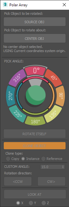
Polar arrayPermalink
Rotate / Clone an object around a center or reference object.
- Select an object to operate on.
- Activate the tool, a dialog will open. Pick a center object.
- Clicking on the colored slices of the dial will move the object X degrees around the center object.
- Rotate itself option will rotate the object over itself the same amount of degrees.
- The Clone object option can will clone the object with each angular movement, making circular arrays.
- Use Custom angle and the CW (clockwise) or CCW (counter clockwise) for any custom increment instead of the predefined 45° multiplies of the dial.
LOOK AT Will apply to the object a look at animation constraint, keeping the object always “looking” at the center.
Floater dialogPermalink
Merge and Explode toolsPermalink
This tools offers some enhanced functionality to the default available attach/detach functions specific for Editable polys, Meshes, and splines. It will work with multiple selected objects of the supported types, and there is no need to go to the modifier command panel or modelling ribbon tab.
- Explode will detach geometry elements and spline shapes to individual objects.
- Merge will Combine geometry and splines in one object.
Supported object types:
| Primitives |
| Edit Poly |
| Edit Mesh |
| Splines |
![]()
Edge length toolPermalink
Change the length of selected edges. (Works only with Editable Poly objects)
- Select the Editable Poly object and start the tool.
- Select a set of edges you want to modify and select a reference vertex for each edge, it will be used as a base point to set the direction of the operation. If no vertex is selected the tool will use the first one that finds.
- Options: Max, minimum, and average length, custom value.
![]()
Align verticesPermalink
Align a selection of vertices in a straight line.
- Select the vertices you want to align. alternatively, select a edge loop or some consecutive edges.
- Start the tool. Choose a base point to begin drawing a line that will be used to align the vertices.
- Choose an endpoint to determine the direction of the line. The vertices will be repositioned over the line, to the closest point to the original position.