refGuides
refGuides, spatial reference helpersPermalink
refGuides toolset allows to create construction guides for accurately position and model objects. This guides can act as rulers, displaying custom measurement units in the viewport.
The main functionality of this tool set consist in the creation of tree types of reference objects : linear guide, protractor and point.
Another feature is the ability to place intersection marks where linear guides intersects in space. Use this feature with the Intersection points option, or holding the ALT key during placement.
![]()
Guides placementPermalink
Three creation modes are available:
Free space modePermalink
This mode place a guide by determining a direction from two points.
- Pick a base reference point.
- Pick a second reference point determining the direction of the guide.
Pressing SHIFT will lock the tracking to orthogonal coordinates.
Orthogonal space modePermalink
- Pick a reference point, it will act as a center of the orthogonal space.
- Move the mouse around to change the direction or snap to a point.
Press CTRL during axis selection for Z axis restriction.
Polar space modePermalink
- Pick base point. A circular gizmo displays in the viewports, representing a construction plane.
- Rotation point 1: Pick Z axis gizmo rotation reference point.
- Rotation point 1: X or Y axis rotation points.
- Press ALT while tracking any gizmo rotation to snap angle values.
- Press SHIFT to change direction, CTRL to change axis.
- Rotate the mouse around to select the angular component.
- “Polar mode angle” option sets the angular increment. It’s accessible from the ribbon, the UI creation mode or the Options dialog.
- Press ALT during last placement tracking to override intersection points ON/OFF setting.
- The tools have a “continued creation” mode for placing more than one guide in one action.
![]()
Line guidePermalink
Intersection pointsPermalink
This feature allows to place reference point, acting as a snapping mark, where the reference guide lines intersects in space.
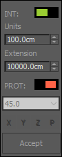
Guides parametersPermalink
Line guides have two parameters: Units and Extension.
- Units provide a subdivision scale for the guide. Used to snap objects to, or as a measure ruler.
- Extension determines how long the guide will be.
The UI option for the creation modes shows a floater with the general settings for the guides, protractor placement and intersection points option. Right clicking on the dialog pops up a context menu with more options.
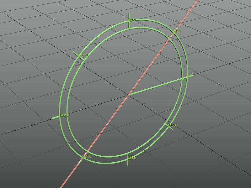
Protractor guidePermalink
Tool for displaying and snapping angular values. The same placing methods described for the reference line tool are available for the protractor, a exception of the UI mode, since its included in the guide line UI.
![]()
Reference points ToolPermalink
Trace temporary reference lines and place points at intersections. In difference with 3ds Max Helper points, this custom reference points will work with vertex snap.
Line tracing options:
- Hold SHIFT when tracking a line second reference point to enable ORTHOGONAL direction override.
- Press SHIFT / when picking first point of line for orthogonal placement mode
- Press ALT when picking first point of line for polar placement mode
![]()
Viewport information toolsPermalink
Use the guides as a ruler display in viewport unit steps
- Live info: Display units for the current selected guide.
- Live info+: Display units for all the guides in the current view (skips hidden or isolated guides).
![]()
refGuides ObjectsPermalink
When using any of the “refGuides” tools, a custom Shape object is created for / Lines / Protractors / intersection points / with options available from the command panel for tunning their settings: Line extension, units scale; Protractor angle marks and radius; Intersection point display style and size.[*]
refGuides additional toolsPermalink
- Delete all guides in scene.
- Lock guides after creation.
![]()