Measure Tools
Distance
The Distance tool functions as a measuring tape with live visual feedback.
How to Use
- Pick a start point.
- Track the distance.
- Pick an end point to measure again. Each measurement remains displayed until the tool is exited.
- SHIFT: Restricts the tape to the XYZ axes (orthogonal mode).
The last measurement result is copied to the clipboard and traced to the listener after finishing the tool.
Contiguous (Chain) Dimension Line
How to Use
- Pick a measurement start point.
- Continue picking points to add measurements.
- Finish the tool with a right-click.
SHIFT: Restricts the second point to orthogonal mode. CTRL: Enables axis-lock during tracking.
Measurements are copied to the clipboard and traced to the listener.
Arc length
Measure the length of an arc defined by three points. The arc can be oriented in any position.
How to Use
- Pick a start point
- Pick the arc end point
- Pick a point inside the arc (bulge).
In addition of the arc length, the tool also provides the radius length and marks the center.
Circle diameter or radius
Measure any circumference diameter by selecting 3 points.
How to Use
- Pick the first point on the circle.
- Pick the second point on the circle.
- Pick the third point on the circle.
Dimension line will be positioned across the circle, ending in the 3rd point, showing diameter and radius values.
Press SHIFT when starting the tool to measure the radius instead of diameter.
Find arc or circle center
Use three points to locate the center of an arc or circle. The tool positions a point mark at the center.
How to Use
- Pick the first point on the arc or circle.
- Pick the second point on the arc or circle.
- Pick the third point on the arc or circle.
Press SHIFT while starting the tool to position and align a circle shape.
Divide Distance
Set reference points to divide a distance into equal segments.
How to Use
- Pick the distance start point.
- Pick the distance end point.
- Move the mouse toward the start or end point to set the number of segments.
- SHIFT: Restricts the second point to orthogonal mode.
You can use the Divide distance | input mode tool to type the subdivision steps instead of using mouse tracking. Note: Orthogonal tracking (SHIFT) has an axis-lock feature: Hold SHIFT, and with vertex snap activated, move the cursor to a vertex and press CTRL. The tracking will be restricted to the nearest axis, allowing you to track any point while the line remains locked to that axis. This feature works in all tools with an orthogonal tracking feature.
Working with Measurements: Distance History
The “Distance History” dialog stores the measures taken with the “Measure Distance” or “Continued Distance” tools, allowing you to re-display them and customize their appearance. You can also create standard spline-based dimension objects to display and render the taken measurements. Both functionalities are integrated into the UI of the “Distance History” tool.
Distance History
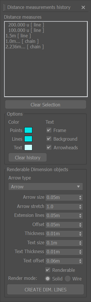
Selecting one or multiple items in the “Distance Measures” or “Continued Distance Measures” listbox will re-display them in the viewport.
Actions
- Clear selection: Deselect all items, turning off their display.
- Clear values: Reset the history, clearing all stored measurements.
- Update: This action is needed when you take more measurements with the dialog open. It will update the lists by adding the new entries. It will also update any changes in the color or text background/frame.
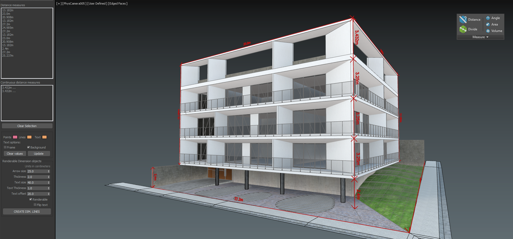
Dimension Objects
Create dimension lines with measurement annotations, allowing you to render the taken dimensions. Standard Spline and Text shapes will be created.
Parameters
- Arrow size: This parameter controls the width and height of the dimension line arrows.
- Thickness: The thickness of the line geometry.
- Text size: The size of the text label.
- Text thickness: Text labels are created with an extrusion modifier. This controls the extrusion amount.
- Text offset: The distance between the dimension line and the text.
- Renderable: Enables geometry rendering in the output and viewports. Enabled by default.
- Flip text: Sometimes the dimension text can be flipped (right to left); check this to address the issue.
Parameter spinner units are in centimeters.
Please note that the text will be oriented left-to-right based on the current view. Expect unpredictable results in orthogonal views.
Angle
Measure any angle by 3 points.
How to Use
- Pick the angle base point.
- Pick the first reference point to mark a direction vector. The tool will track the angle comprehended between the first direction vector and the current mouse position or vertex snap (with center at the base point).
- Pick the second reference point to end.
Hold SHIFT while tracking the second and third points for orthogonal mode. The angle measurement is copied to the clipboard and traced to the listener.
Area
Measure the area of a polygon defined by a series of points.
How to Use
- Pick points to define the polygon’s vertices.
- Right-click to finish and calculate the area.
The area measurement is copied to the clipboard and traced to the listener. Orthogonal mode is available for the measure tool, press SHIFT between point picks.
Volume
Cubic volume measure tool. It’s not restricted to selected object mass, instead is measured as an empty space container box.
How to Use
- Pick two points representing the start and end point of a box diagonal line.
- The measured volume of the box will be traced to the listener.
Angle between two faces
Measure the angle between two faces.
How to Use
- Start the tool.
- Pick the first face and then a second one to inquiry the angle.
- Two marks indicating the points and face normals will be drawn, along with a line connecting them and a text showing the angle in this format: ANGLE---COMPLEMENTARY ANGLE
- The measurement will be printed to the listener, so you can copy and use these values.
Note that this tool will not work when you have flipped normals, so check for inverted normals first.
Angle between two edges
- Select two edges in an Editable poly or mesh object.
- Check the tool macro button to show the angle between these two edges. Check the button again to change the object or to disable the tool.
Spatial Info
Displays information about an object’s dimension and transformation
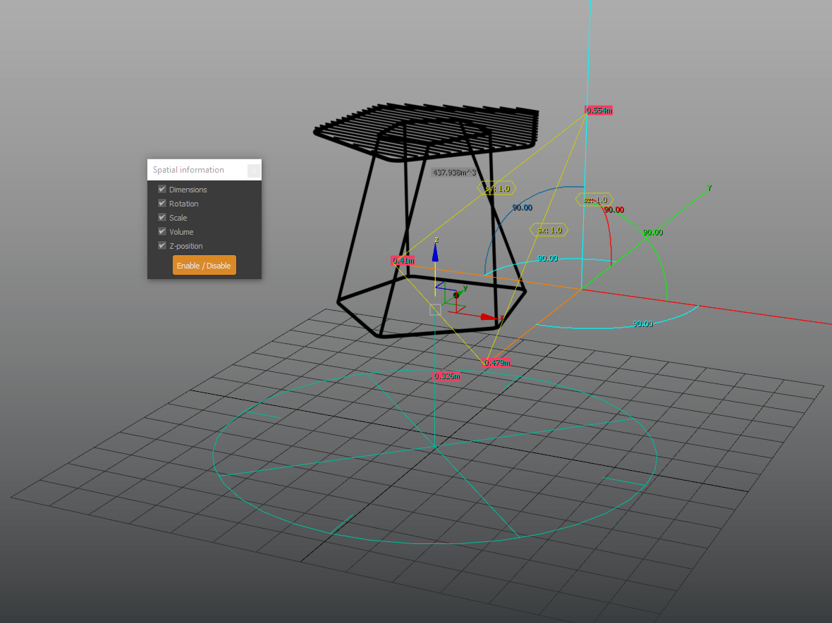
Home grid size
Displays a reference gizmo with 3 rules towards the XYZ axes indicating the Active Grid spacing units.