Object-Related Tools
1D Array (Clone Between)
The 1D Array tool places clones at subdivision marks between two points.
How to Use
- Pick the distance start point.
- Pick the distance end point.
- Move the mouse to set the number of segments.
- SHIFT: Enables orthogonal mode while tracking the second point.
- Pick the object to clone when prompted.
Note: Orthogonal tracking includes an axis-lock feature. Hold SHIFT and activate vertex snap, then press CTRL to restrict tracking to the nearest axis. This feature is available in all tools with orthogonal tracking.
Alternate Mode: Press SHIFT when activating the tool to place clones at the midpoint of segments.
Interactive 2D Array
Quickly create a 2.5D array of objects by picking points in the viewport.
How to Use
- Select the object to clone.
- Define a rectangular area:
- Base point.
- Third point sets the width. SHIFT: Inverts the up-direction.
- Move the mouse to select the number of rows. Left-click to confirm.
- Move the mouse again to define the number of columns. Click to finish.
Pattern Array
Create complex, rule-based object arrays like walls and mosaic patterns.
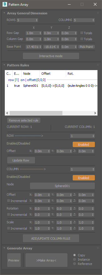
- Array Dimension
- Rows and Columns: Set the amount of rows and columns for the array. Array dimension will be nRows x nColumns. (nColumns per row).
- Checking “Totals” for Rows and Columns separation will use the XYZ values as total distance for rows or columns extension.
- Interactive mode allows setting the array dimension parameters interactively from the viewport.
- Add Rules
- Set a row number in the spinner to add rules to. Press “Update Row” if you change the offset parameters for the currently selected row number. Unchecking “Enable” will turn off the current row, but it’s still used for calculations.
- Set the current column for the row. Each added rule will “fill” a cell in the row. 2.1 Pick the node to use. 2.2 Set offset, rotation, and scale values. Un-checking “Enabled” will leave a “hole” in the array, without breaking the rules.
- Once you finish setting the new column, or update the currently selected row, press “ADD/UPDATE”, and check in the list view if the rule was successfully updated.
Note: The preview needs to be updated after making changes to the rules.
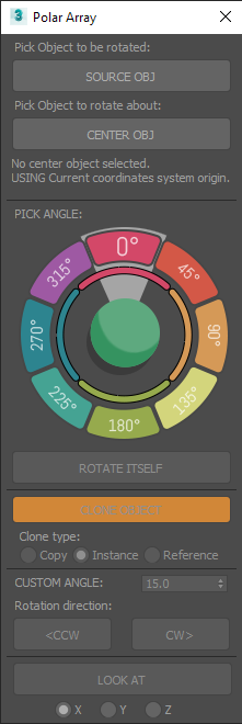
Polar Array
Rotate or clone an object around a center point or reference object.
How to Use
- Select an object to operate on.
- Activate the tool, and a dialog will open. Pick a center object.
- Clicking on the colored slices of the dial will move the object by X degrees around the center object.
- The “Rotate itself” option will rotate the object on its own axis by the same number of degrees.
- The Clone object option will clone the object with each angular movement, creating circular arrays.
- Use “Custom angle” and the CW (clockwise) or CCW (counter-clockwise) buttons for any custom increment instead of the predefined 45° multiples on the dial.
LOOK AT will apply a look at animation constraint to the object, keeping it always “looking” at the center.
Floater Dialog
Merge and Explode Tools
These tools enhance the default attach/detach functions for Editable Polys, Meshes, and splines. They work with multiple selected objects of supported types, eliminating the need to access the modifier command panel or modeling ribbon tab.
- Explode: Detaches geometry elements and spline shapes into individual objects.
- Merge: Combines geometry and splines into a single object.
Supported Object Types:
| Primitives |
|---|
| Edit Poly |
| Edit Mesh |
| Splines |
Edge Length Tool
Modify the length of selected edges. (Works only with Editable Poly objects.)
How to Use
- Select the Editable Poly object and start the tool.
- Select a set of edges to modify and choose a reference vertex for each edge. This vertex serves as the base point for setting the operation’s direction. If no vertex is selected, the tool uses the first one it finds.
- Choose from the following options: Max, Minimum, Average Length, or set a Custom Value.
Align Vertices
Align a selection of vertices in a straight line.
How to Use
- Select the vertices to align. Alternatively, select an edge loop or consecutive edges.
- Start the tool and choose a base point to begin drawing a line for alignment.
- Choose an endpoint to determine the line’s direction. The vertices are repositioned along the line, closest to their original positions.
Select faces by area
Select polygons by area.
- Select an editable poly object, start the tool.
- Use the min. and max. values to limit a value threshold.
- Use the invalid faces check button to quickly select faces with zero area.
Works only with Editable Polys
Select invalid faces
Select faces with zero area and invalid vertex count. Useful for cleaning imported meshes.
Select an editable poly object to start the tool. Use it with imported meshes to quickly find and fix problematic geometry.
Best enter sub object selection (face mode) before starting the tool.
Works only with Editable Polys