User Guide
refGuides, spatial reference helpers
refGuides toolset allows to create construction guides for accurately position and model objects. This guides can act as rulers, displaying custom measurement units in the viewport.
The main functionality of this tool set consist in the creation of tree types of reference objects : linear guide, protractor and point.
Another feature is the ability to place intersection marks where linear guides intersects in space. Use this feature with the Intersection points option, or holding the ALT key during placement.
![]()
Guides placement
Three creation modes are available:
Free space mode
This mode place a guide by determining a direction from two points.
- Pick a base reference point.
- Pick a second reference point determining the direction of the guide.
Pressing SHIFT will lock the tracking to orthogonal coordinates.
Orthogonal space mode
- Pick a reference point, it will act as a center of the orthogonal space.
- Move the mouse around to change the direction or snap to a point.
Press CTRL during axis selection for Z axis restriction.
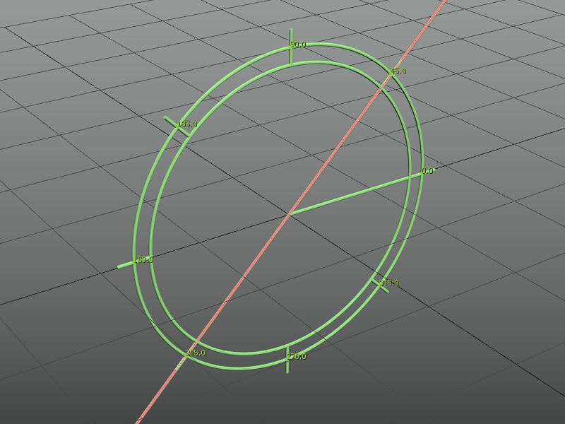
Polar space mode
- Pick base point. A circular gizmo displays in the viewports, representing a construction plane.
- Rotation point 1: Pick Z axis gizmo rotation reference point.
- Rotation point 1: X or Y axis rotation points.
- Press ALT while tracking any gizmo rotation to snap angle values.
- Press SHIFT to change direction, CTRL to change axis.
- Rotate the mouse around to select the angular component.
- “Polar mode angle” option sets the angular increment. It’s accessible from the ribbon, the UI creation mode or the Options dialog.
- Press ALT during last placement tracking to override intersection points ON/OFF setting.
- The tools have a “continued creation” mode for placing more than one guide in one action.
![]()
Line guide
Intersection points
This feature allows to place reference point, acting as a snapping mark, where the reference guide lines intersects in space.
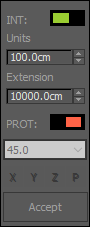
Guides parameters
Line guides have two parameters: Units and Extension.
- Units provide a subdivision scale for the guide. Used to snap objects to, or as a measure ruler.
- Extension determines how long the guide will be.
The UI option for the creation modes shows a floater with the general settings for the guides, protractor placement and intersection points option. Right clicking on the dialog pops up a context menu with more options.
Protractor guide
Tool for displaying and snapping angular values. The same placing methods described for the reference line tool are available for the protractor, a exception of the UI mode, since its included in the guide line UI.
![]()
Reference points Tool
Trace temporary reference lines and place points at intersections. In difference with 3ds Max Helper points, this custom reference points will work with vertex snap.
Line tracing options:
- Hold SHIFT when tracking a line second reference point to enable ORTHOGONAL direction override.
- Press SHIFT / when picking first point of line for orthogonal placement mode
- Press ALT when picking first point of line for polar placement mode
![]()
Viewport information tools
Use the guides as a ruler display in viewport unit steps
- Live info: Display units for the current selected guide.
- Live info+: Display units for all the guides in the current view (skips hidden or isolated guides).
![]()
refGuides Objects
When using any of the “refGuides” tools, a custom Shape object is created for / Lines / Protractors / intersection points / with options available from the command panel for tunning their settings: Line extension, units scale; Protractor angle marks and radius; Intersection point display style and size.[*]
refGuides additional tools
- Delete all guides in scene.
- Lock guides after creation.
![]()
Transform tools
![]()
reference Rotation
Rotates an object about a direction axis and a reference point
First, select the object you want to rotate.
- Pick base point. this point will act as rotation center.
- Pick point for rotation axis.
- Rotate from line (Pick reference point).
- Move mouse to set rotation angle and direction. Snap to point or press SHIFT to lock angle steps.
Hold CTRL key when performing the last step (rotation) the tool will rotate an instance of the object instead.
![]()
local reference Rotation
2-point CAD-like rotation. Rotates an object about a local coordinates direction axis and a reference direction
- Pick base point.
- Pick rotate-from point.
- change XYZ axis while tracing rotate-from point:
- X axis: SHIFT
- Y axis: CTRL
- Z axis: Default
- Track rotation angle and direction. Press SHIFT to restrict angle steps.
![]()
reference Scale
Used to scale an object with a reference length to stretch and a target length; works as a 4-point scale method.
> First, select the object to scale.
The tool works picking two reference distances, one representing a reference length to stretch up or down, and a second one representing the new distance.
- Pick Base point. This point will act as base for the operation, also marks the original length start.
- Pick second point for the original length line. Note that the direction of the line will be the direction of the operation.
- pick Base point for the reference length.
- pick End point for the reference length.
- Pressing SHIFT while tracking second points will restrict the lines to Orthogonal space*.
- Pressing SHIFT When activating the tool will keep the objects proportion for the scaling operation.
- The reference scale tools has three modes:
- Normal: Operation done in world space.
- In context: Operation done in local coordinates.
- Xform: Instead of direct transformation, it applies a Xform modifier to the target object.
![]()
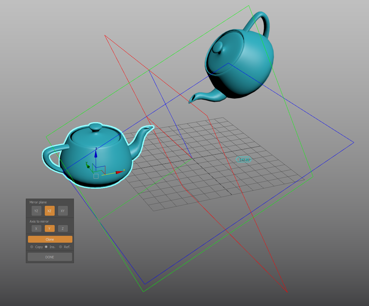
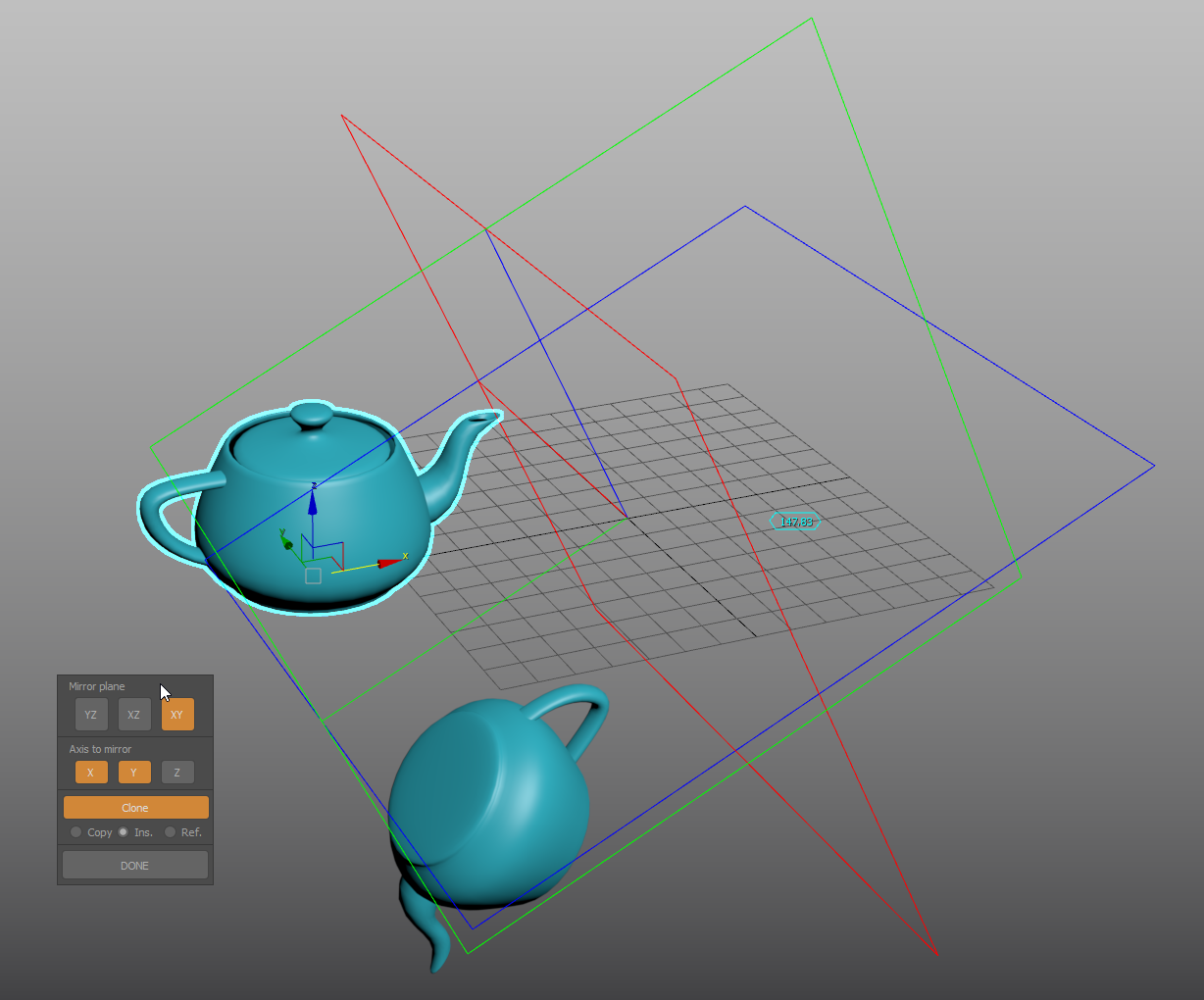
Mirror tool
Interactive mirror tool with complex mirror planes alignment.
- Start with positioning the reference3-plane gizmo, picking a center point for the mirror operation.
- Orient the gizmo with points for direction, yaw, Pitch, Roll and offset angle.
- Gizmo alignment: set the gizmo start position by picking a direction vector. Use SHIFT for orthogonal tracking, and SHIFT+CTRL to lock the gizmo and track Z axis.
- YAW angle: (or XY plane): Use RIGHT-CLICK to skip, SHIFT for angle snapping and ALT to invert direction.
- Pitch (YZ plane, along X axis) and Roll (XZ plane, along Y axis): Use RIGHT-CLICK to skip, CTRL to change from Pitch to Roll, SHIFT for angle snapping and ALT to invert direction.
- Set or skip the offset angle
- Finally, select the objects and use the options in the dialog to enable or disable the mirror axes or planes.
![]()
Move and align (1D Align tool)
Align objects using two directions from a common base point.
- Select a target node. Pick a reference point and a target point to displace the node to a new position. This is a free space operation.
- Pick one point to set a reference direction, and a target point to match the original direction to it.
- Use Right Click or ESCAPE to end the tool.
![]()
3 points align
Relocate a node from three pairs of points, from an origin position to a target position.
- Select the node you want to reposition
- Pick first (A1) reference position and match it with a destination position (A2). “A” is the base point for the transformation
- Pick second (B1) reference position and match it with a destination position (B2)
- Pick first (C1) reference position and match it with a destination position (D2)
- An axis gizmo will be displayed in the reference and start locations representing the origin (ABC1) and result (ABC2) coordinate systems.
- Left Click once more to invert the transformation, or exit the tool with Right Click
![]()
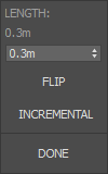
reDimension
Real world units scaling in a direction. Change object’s height, length or width (or proportional length-width etc..) to a desire dimension.
- Select the object and pick a base reference point.
- Pick reference distance / direction end.
- Pressing SHIFT while tracking second point will restrict the direction to orthogonal space*.
- Set new dimension on the Dialog UI.
- Incremental option will add / subtract the value form the former distance.
Floater dialog
![]()
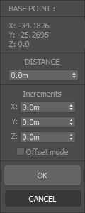
Position Offset
Precise referential movement from a target point, and specified direction
- Select objects to move.
- Pick an Origin point for the movement trajectory.
- Pick an End point.
- A dialog will open to set the distance. A reference mark will display the displacement from the Base point along the trajectory line. X Y and Z spinners stets the distance by correlated axis increments; enabling “offset mode” will shift the position of the reference mark from the trajectory
- Incremental mode will change the target point to the Origin point instead of the default End point.
- You can use this tool in editable poly mode, selecting the sub objects to be moved first.
![]()
Reference move
CAD-like Move tool that uses two (origin and destination) reference points.
- Select the objects you want to move.
- Start the tool; Pick an origin ref. point (be sure to enable snaps)
- Pick a destination point to displace the origin point to.
![]()
Swap transform
Select a collection of objects (will follow the selection pick order) and cycle their transform from one to the next.
![]()
Random swap transform
Randomly swap position, rotation and scale between the selected objects.
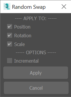
Floater dialog
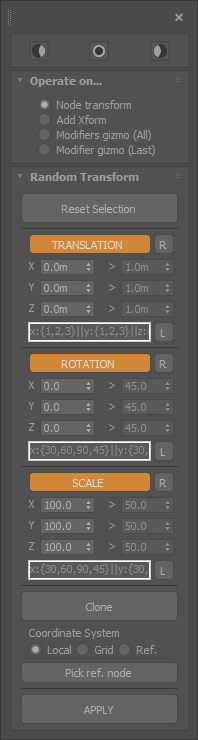
Random transform
Tool packed with several options to randomize and clone nodes.
- Can be used to directly modify the node transform, add an XForm modifier, or transform applied modifiers gizmo’s.
- Set constant, by range or a scripted list of values to apply the transform.
- Apply the transform in Grid, Local, or Reference coordinate system. To use the later mode, pick a reference node first.
Arrange objects
![]()
Arrange objects (interactive)
Distribute or redistribute objects (equally spaced) on a linear direction. This variant of the tool tracks the objects new position’s with marks in the viewport
- Select the object set to rearrange.
- Pick the direction line START POINT
- Track the end of the line. Before picking the END POINT to finish the operation, use these options:
- Press SHIFT to conform to the underlying surfaces
- Press SHIFT to orient to the underlying surfaces
![]()
Arrange objects (real-time)
Distribute or redistribute objects (equally spaced) on a linear direction. This variant of the tool tracks the objects new position’s in real time. it could be slow with complex geometry
- Select the object set to rearrange.
- Pick the direction line START POINT
- Track the end of the line. Before picking the END POINT to finish the operation, use these options:
- Press SHIFT to conform to the underlying surfaces
- Press CONTROL to orient to the underlying surfaces
![]()
Arrange objects (start-end objects)
Distribute or redistribute objects (equally spaced) on a linear direction. Direction and length of the distribution determined by the position of two objects:
- Select the START OBJECT
- Select the END OBJECT
- Select the objects to distribute between them.
Press the TOOL BUTTON+SHIFT to conform and align the objects to the underlying surfaces.
![]()
Drop objects
Drop objects on underlay surfaces.
Press SHIFT when activating the tool to align the objects to the surface form.
Measure tools
![]()
Divide distance
Set reference points to divide a distance.
- Pick distance start point.
- Pick distance second point.
- Move the mouse towards the start or end point to set segments amount.
- Press SHIFT while tracking second point for orthogonal mode.
You can use the Divide distance | input mode tool to type the subdivision steps instead of mouse tracking. Note: Orthogonal tracking (SHIFT) has a axis-lock feature: Keep SHIFT pressed, and having vertex snap activated, move the cursor to a vertex and press CTRL, the tracking will be restricted to the nearest axis, and then you can track any point, the line will lock to that specific axis. This feature works in all the tools that has a orthogonal tracking feature.
![]()
Distance
Measure tape with live visual feedback.
- Pick a start point.
- Track distance.
- Pick an end point to measure again. A tape for each measurement will remain displayed until tool exit.
- After picking the first point, press SHIFT to restrict the tape to XYZ axes (orthogonal mode).
The result of the last measure will be copied to the clipboard and each measure is traced to the listener after finishing using the tool.
![]()
Contiguous (chain) dimension line
- Measurement start point
- Continue picking points to add measurements
- Finish the tool with right-click
Hold SHIFT while tracking second point for orthogonal mode, then press CTRL for axis-lock. Measurements are copied to the clipboard and traced to the listener.
![]()
Working with measurements: Distance history
The “Distance history” dialog will store the taken measures with the “measure distance” or “continued distance” tools, allowing to re-display them and customize the appearance. You can also, create (standard-spline based) dimension objects to display and render the taken measurements. Both functionalities are integrated in the dialog UI of the “Distance history” tool.
Distance history
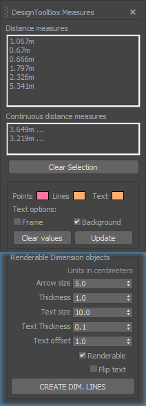
Selecting one or multiple items in the listbox of “Distance measures” or “Continued distance measures” wil re-display them in the viewport.
Actions
- Clear selection: Deselect all items, turning off their display.
- Clear values: Reset the history, clearing all stored measurements.
- Update: This action is needed when you take some more measurements, with the dialog open. It will update the lists adding the new entries. It will also update any change in the color or text background/frame changes.
Dimension objects
Create dimension lines with measure annotation allowing to render the taken dimensions. Standard Spline and text shapes will be created.
Parameters
- Arrow size: This parameter controls the width and height of the dimension line arrows.
- Thickness: Thickness of the lines geometry.
- Text size: The size of the text label.
- Text thickness: Text labels are created with an extrusion modifier. This controls the extrusion amount.
- Text offset: Distance between the dimension line and the text.
- Renderable: Enables geometry rendering in output and viewports. On by default
- Flip text: Sometimes the dimension text can be flipped (right to left) check this to address this.
Parameter spinners units are in centimeters.
Please note that, the text will be oriented left -> right, based on the current view. Expect unpredicted result on orthogonal views.

![]()
Angle
Measure any angle by 3 points.
- Pick angle base point.
- Pick first reference point to mark a direction vector. The tool will track the angle comprehended between the first direction vector and the current mouse position or vertex snap (with center at the base point).
- Pick second reference point to end.
![]()
Area
Pick points to draw an a closed polygonal region and measure its area.
- Start picking points to draw an enclosed polyline.
- Press right click to finish the measure. The result is traced to the listener.
Orthogonal mode is available for the measure tool, press SHIFT between point picks.
![]()
Volume
Cubic volume measure tool. It’s not restricted to selected object mass, instead is measured as an empty space container box.
Pick two points representing the start and end point of a box diagonal line. The measured volume of the box will be traced to the listener.
![]()
Angle between two faces
Measure the angle between two faces.
- Start the tool.
- Pick the first face and then a second one to inquiry the angle.
- Two marks indicating the points and face normals will be drawn, along with a line connecting them and a text showing the angle in this format: ANGLE—COMPLEMENTARY ANGLE
- The measurement will be printed to the listener, so you can copy and use these values.
Note that this tool will not work when you have flipped normals, so check for inverted normals first.
![]()
Angle between two edges
- Select two edges in an Editable poly or mesh object.
- Check the tool macro button to show the angle between these two edges. Check the button again to change the object or to disable the tool.
Spatial Info
Displays information about an object’s dimension and transformation
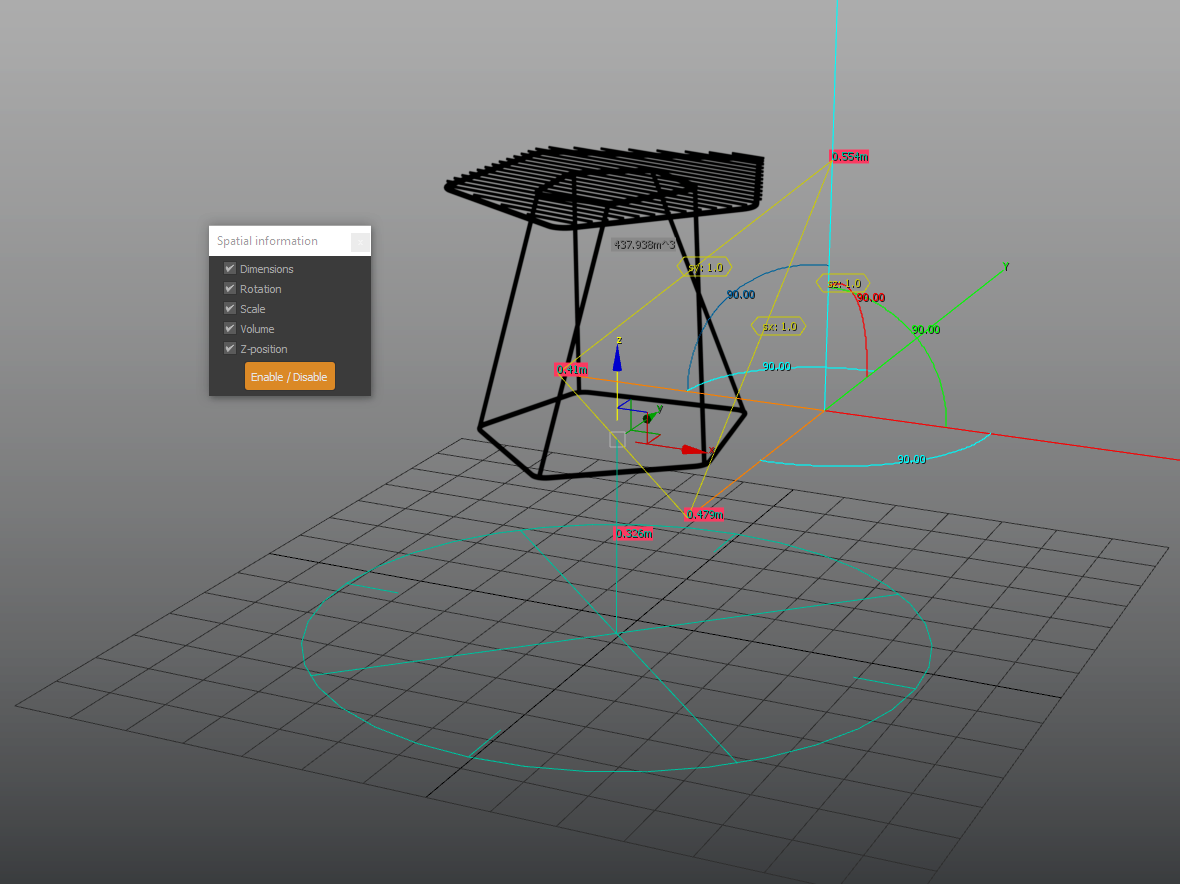
Home grid size
Displays a reference gizmo with 3 rules towards the XYZ axes indicating the Active Grid spacing units.
Configuration dialog
Provides settings to change the guides color, layer name, intersection points behavior and object type.
refGuides options
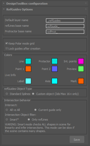
- [*] Custom Object mode (On by default) is only available for 3Ds Max 2016 and up.
- Smart intersection mode will consider any planar shape on the scene as a guide. While resource consuming, it can place intersection points on imported CAD drawings. for example.
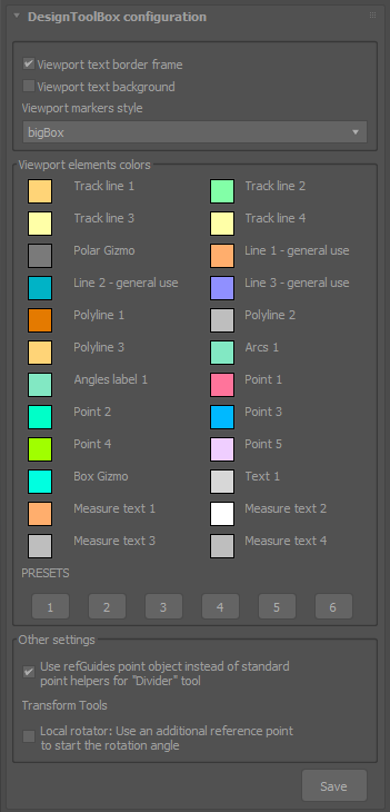
Viewport elements colors
You can change the color palette used to represent points marks, lines and other kind of visual helpers within the tools. Change the colors in the pickers or use one of the presets.
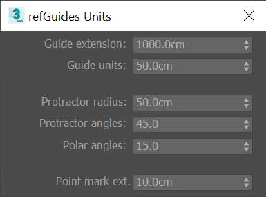
refGuides units configuration
- Configure the default values for the guidelines extension and unit scale.
- For the protractor change the radius, angle marks and angle snap for the polar positioning function.
- Set the size of the point markers
Transform and measure tools units configuration
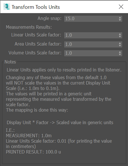
- Linear Units apply only to results printed in the listener.
- Changing any of these values from the default 1.0 Will NOT scale the values in the current Display Unit Scale (i.e.: 1.0m to 0.1m).
- The values Will be printed in a generic unit, representing the measured value transformed by the scale factor.
- The mapping is done this way: Display Unit * Factor -> Scaled value in generic units.
I.E.:
MEASUREMENT: 1.0m
Linear Units Scale factor: 0.01 (for printing the value in centimeters)
PRINTED RESULT: 100.0 u
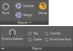
Pivot and coordinates related tools
![]()
Pivot tools
Pivot repositioning commands
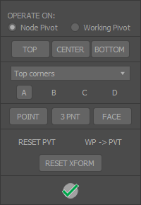
While there already are tools available to reposition an object’s center pivot, this one groups them in a convenient UI, that pops down from the toolbar or ribbon button.
LEFT CLICK on any button to keep the UI open, or RIGHT CLICK to instantly close it.
- CENTER, TOP, BOTTOM: Most common operations, can be used directly from a dedicated macro.
-
Top corners / middle / bottom corners: Box model reference locations. A B C D buttons represents a corner point. - 3 PNT: Position pivot from three points (base point > Y axis > X axis) keep SHIFT pressed to flip Z direction.
- This also can be used to set a Working Pivot.
- FACE: Select an editable poly face and puts the pivot on its center, aligned to the face normal.
- This also can be used to set a Working Pivot.
- RESET PVT: Resets the pivot to its original location.
- RESET XFRM: Shortcut for the built in reset object Xform.
Pivot to Snap point
Quickly move an object’s pivot to a snapping point. Works with any snap type. If no object is selected, the tool will reposition the pivot of the object where the snap is displayed (if any)
This tool needs to be assigned to a keyboard shortcut!
![]()
Transform locks
Convenient shortcuts to enable / disable standard transformations locks on the current selected objects.
- All: Lock / unlock all transformations (Move, scale and rotate)
- Move lock
- Rotation lock
- Scale lock
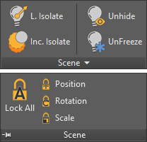
Scene organization tools
Local isolate
Isolate / unisolate selected object and set an active work grid in its local coordinates.
Note: If more than one object is selected, Local isolate will use the first object in the selection to set the grid.
Incremental isolation
re-Isolate within current the selection.
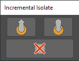
The tool will open a floater dialog with three buttons. “LEVEL UP”, “LEVEL DOWN” and “CLOSE”. Select some nodes and press LEVEL UP to isolate them. Press LEVEL DOWN to restore the previous isolated nodes, or exit isolation mode if no previous level is registered. Closing the tool will exit isolation mode.
![]()
unHide by selection
This tool will temporally display all hidden objects (and hide visible ones). Select the ones you want to unhide and Press “Done” on the floater.
![]()
unFreeze by selection
This tool will temporally display all frozen objects (and freeze visible ones). Select the ones you want to unfreeze and Press “Done” on the floater.
![]()
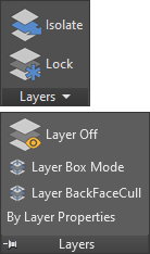
Layer tools
Layer tools will work on the selected node (if any) otherwise they will work in “pick mode”.
| Isolate layer | Isolate-Unisolate selected object/s layer/s. If nothing is selected, you can pick an object in viewport and isolate the respective layer. |
| Lock layer | Locks the layer of the picked/selected node. Press SHIFT when activating the tool to pick frozen nodes/layers. |
| Hide layer | Turn off the layer of the picked node. Press SHIFT when activating the tool to pick frozen nodes/layers. |
| Layer box mode | Set Box mode status for target node layer. Press SHIFT when activating the tool to pick frozen nodes/layers. |
| Layer backface cull | Set BackFaceCull status for target node layer. Press SHIFT when activating the tool to pick frozen nodes/layers. |
Eyedropper tools
![]()
Replicator
Replace any node with an instance or reference of another source node.
- Pick source node.
- Pick nodes to be replaced.
- DEFAULT: Instance replacement
- SHIFT while picking objects will create a reference.
- By Default, replicator will keep the original node material and transformation. to replace the transformation, activate the checkbox in the ribbon or the check button macro. Note that the original position is always maintained.
- Multitarget toggle will disable multiple targets.
![]()
Eyedropper
Properties, modifiers and appearance copy tool, from a source object to a target object or objects*
Note that, Eyedropper will replace any matching or similar property, regardless of the node class. I.E: You can copy the diameter of a circle shape to a sphere object, and so on. UVW map copy will copy applied UVW modifiers and attempt to copy direct mesh mapping, so if a editable poly or mesh is collapsed, there is a chance their mapping coordinates will be copied.
MultiTool
Will copy the active settings on the filters dialog:
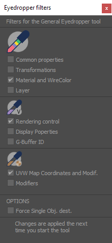
Eyedropper modes
Additional available modes:
| Visual appearance |
| Material |
| non-Topology dependent modifiers |
| Standard transformations |
| UVW mapping |
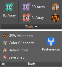
Object related tools
![]()
1D Array (Clone Between)
Set subdivision marks between two points, and place a clone on each mark
- Pick distance start point.
- Pick distance second point.
- Move the mouse towards the start or end point to set segments amount.
- Press SHIFT while tracking second point for orthogonal mode.
- Pick the object to clone when prompted.
Note: Orthogonal tracking (SHIFT) has a axis-lock feature: Keep SHIFT pressed, and having vertex snap activated, move the cursor to a vertex and press CTRL, the tracking will be restricted to the nearest axis, and then you can track any point, the line will lock to that specific axis. This feature works in all the tools that has a orthogonal tracking feature. Alternate mode: Press SHIFT when activating the tool to place the clones at segments midpoint.
![]()
Interactive 2D Array
Quickly create a 2.5D Array of objects, picking points in the viewport.
- Select the object to clone.
- A rectangular area to operate will be delimited:
- Base point
- Second point will determine the height and alignment of the rectangle. Press SHIFT for orthogonal tracking.
- Third and last point sets the width. Keep pressed SHIFT to invert the up-direction
- Move the mouse away from the last point to select the amount of rows. Press left click to finish selecting rows.
- move the mouse again to define columns quantity. press click to finish.
![]()
Pattern Array
Make complex rule-based object arrays; walls, mosaic patterns…
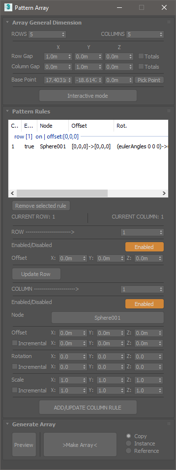
- Array Dimension
- Rows and Columns: Set the amount of rows and columns for the array. Array dimension will be nRows x nColumns. (nColumns per row).
- Checking “Totals” for Rows and Columns separation will use the XYZ values as total distance for rows or columns extension.
- Interactive mode allows to set the array dimension parameters in an interactive way, from the viewport.
- Add rules
- Set a row number in the spinner to add rules to. Press “update Row” if you change the offset parameters for the current selected row number. unchecking “Enable” will turn off the current row, but it’s still used for calculations.
- Set current column for the row. Each added rule will “fill” a cell in the row. 2.1 Pick the node to use. 2.2 Set offset, rotation and scale values. un-checking “Enabled” will left a “hole” in the array, without breaking the rules.
- Once you finish to set the new column, or update the current selected row, press “ADD/UPDATE”, check in the listview if the rule was successfully updated.
Note: The preview needs to be updated after making changes to the rules.
![]()
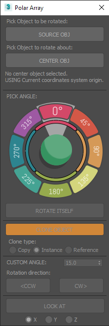
Polar array
Rotate / Clone an object around a center or reference object.
- Select an object to operate on.
- Activate the tool, a dialog will open. Pick a center object.
- Clicking on the colored slices of the dial will move the object X degrees around the center object.
- Rotate itself option will rotate the object over itself the same amount of degrees.
- The Clone object option can will clone the object with each angular movement, making circular arrays.
- Use Custom angle and the CW (clockwise) or CCW (counter clockwise) for any custom increment instead of the predefined 45° multiplies of the dial.
LOOK AT Will apply to the object a look at animation constraint, keeping the object always “looking” at the center.
Floater dialog
Merge and Explode tools
This tools offers some enhanced functionality to the default available attach/detach functions specific for Editable polys, Meshes, and splines. It will work with multiple selected objects of the supported types, and there is no need to go to the modifier command panel or modelling ribbon tab.
- Explode will detach geometry elements and spline shapes to individual objects.
- Merge will Combine geometry and splines in one object.
Supported object types:
| Primitives |
| Edit Poly |
| Edit Mesh |
| Splines |
![]()
Edge length tool
Change the length of selected edges. (Works only with Editable Poly objects)
- Select the Editable Poly object and start the tool.
- Select a set of edges you want to modify and select a reference vertex for each edge, it will be used as a base point to set the direction of the operation. If no vertex is selected the tool will use the first one that finds.
- Options: Max, minimum, and average length, custom value.
![]()
Align vertices
Align a selection of vertices in a straight line.
- Select the vertices you want to align. alternatively, select a edge loop or some consecutive edges.
- Start the tool. Choose a base point to begin drawing a line that will be used to align the vertices.
- Choose an endpoint to determine the direction of the line. The vertices will be repositioned over the line, to the closest point to the original position.
Scene management and rendering related tools
![]()
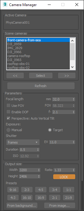
Camera manager
Utility to review scene cameras, assign a custom resolution to each, and add it to a batch render view or state set.
Per-Camera resolution
First Step: Set safe frame On for the camera viewport
Changing resolution / aspect ratio for the active camera in the “Output size” section of the tool will store custom properties for the camera, and the tool will automatically change the render output accordingly when cycling throw the cameras. This allows to quickly render different outputs for each camera.
Please note that the tool will change the current configured render output if you use this feature, and will keep the last setting if you exit the tool and change the view or active camera.
Reviewing cameras
You can either change the camera in the “Scene cameras” list, or use the “Previous” and “Next” buttons. Use the “Refresh” button when you create or delete a camera to update the list. Using “Select” button will select in the scene the active camera.
Open active output preview tool
This will open a new floater dialog, with only a button to set the feature on and off. If the tool is open and enabled, when changing the cameras using the standard 3ds Max method (CTRL+C) the render output will be auto changed to match the settings configured in the “Output size” for the respective camera (if any).
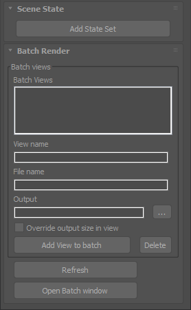
Batch render rollout
- The view will be named with the active camera name and resolution related information.
- After setting the output path one time, the tool will auto format file name and output path for the next views.
![]()
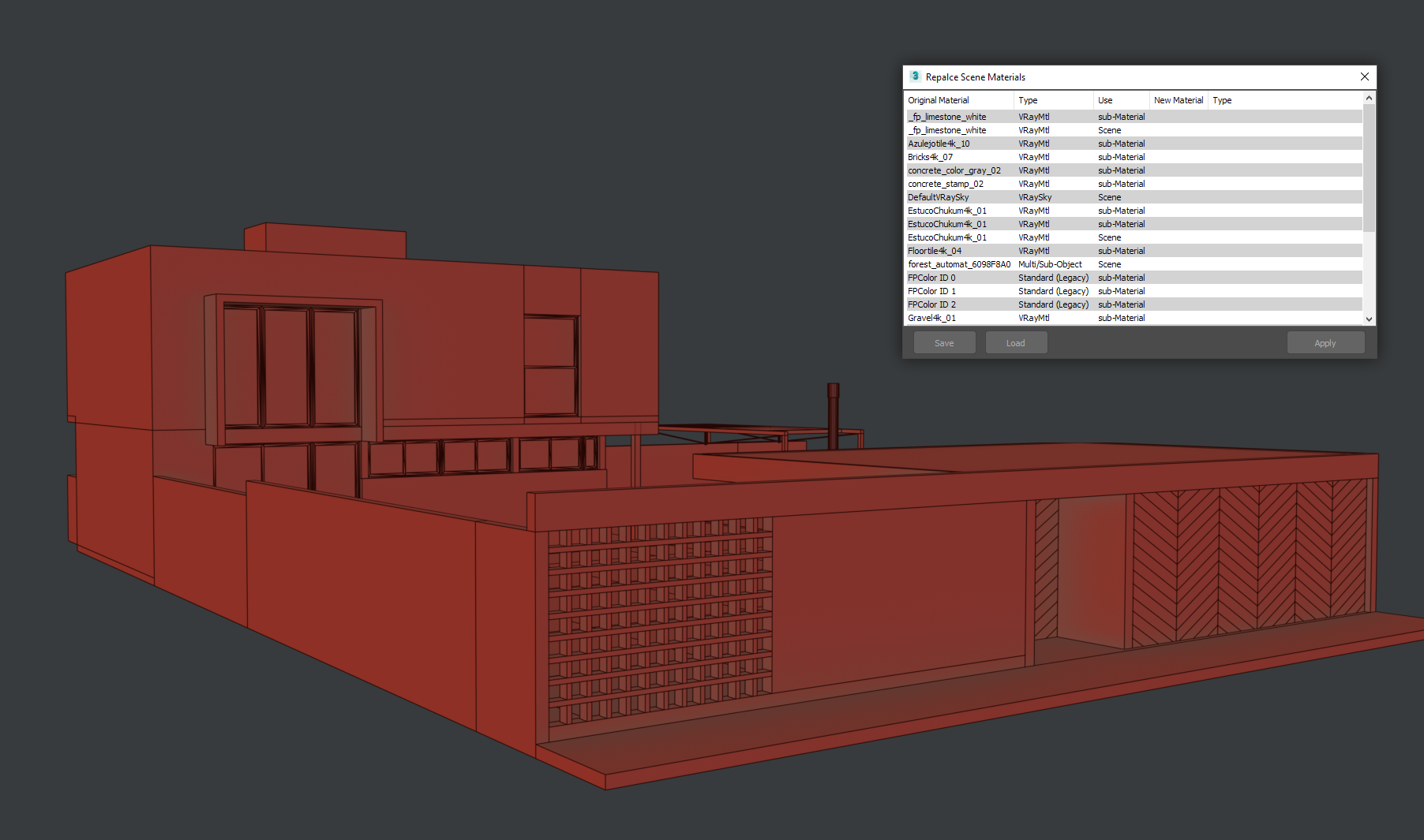
Material replacer
Automate the process of replacing materials. Intended to be used when importing scenes from other sources.
The tool enables to save a list of material correspondences, so if you work in another software with a standardized material library, reassigning materials is as easy to set up correspondences with your 3ds max material library one time, and use the saved list each time you import a scene or object.
Note: When importing some formats, 3ds max auto assigns materials with random names, so use a format like FBX that keeps material information.
Quick material ID Set
Dialog UI for select and set material IDs without the need to dive in the command panel.
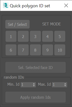
- Works with editable poly only
- You can also select all the faces that has the same ID as the current selected one.
- An additional option allows to randomly set IDs for the selected polygons.
Bitmap multi-loader
Load multiple bitmaps in the scene at once. Bitmap names will be auto assigned with a prefix and the file name. The tool also enables to set the gamma value for the loaded bitmaps.
Bitmap name from file
Change the scene bitmaps name from the default random name to a more meaningful name based on the filename.
Missing textures
Texture maps filename search and replace utility for relocating missing files.
Color clipboard
Dockable color swatches bar

- “+” button populates swatches with random colors.
- LEFT CLICK to fill unused slots.
- press SHIFT + LEFT CLICK for grayscale values.
- press RIGHT CLICK to replace all samples.
- RIGHT CLICK on a sample: Copy or paste color.
- Drag and Drop colors to and form the material editor
- Use the “…” Button to apply HSV adjustments to the colors.
Wireframe colors Adjustment
Adjust HSV values of selected objects wireframe color.
Other material related tools
- Remove materials from selection
- Select nodes without material
- Select faces by ID
- Quick ID set
- Random IDs
Utilities
![]()
Modifiers presets
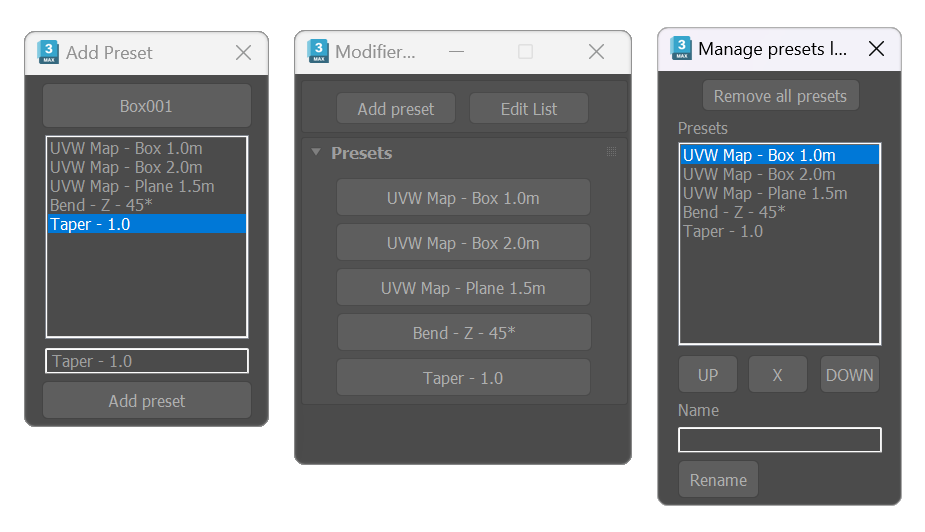
Tool for storing presets for modifier. The tool works by storing values from the modifiers applied to a node. It has three dialogs, the main dialog shows a list of buttons with the presets, one dialog is for adding the presets, and the other is for managing the saved presets.
- Start the tool, use the presets from the list, selecting the object or objects to apply the modifiers to, and clicking the desired preset.
-
- To add presets:
- Select an object with some modifiers applied, and click “Add presets”. Pick an object if nothing is selected.
- Select a modifier from the list, Edit the name, and Add the preset.
- To add presets:
- Use “Edit list” to reset, remove, or rearrange the preset list.
![]()
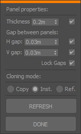
Paneling
Create a grid of panels (boxes or custom geometry) in a planar surface. Originally intended to fast model furniture cabinets and add handles, now is a multi-purpose tool.
- The first step using the Paneling tool is setting the operation surface. Set a rectangular area defined by two points: lower-left and top-right corners.
- A rectangular area to operate will be delimited:
- Base point
- Second point will determine the height and alignment of the rectangle. Press SHIFT for orthogonal tracking.
- Third and last point sets the width. Keep pressed SHIFT to invert the up-direction.
- By default, the tool creates the panels with standard box objects. Start the tool with an object selected, to use it as source for the panels.
- Set Grid Vertical subdivisions moving the mouse towards or away the first point of the area (the lowe left corner), confirm with a left-click; repeat for the horizontal divisions. Each grid cell corresponds with one panel.
- Use the UI to set the gap between panels and thickness. The checkbox next to the spinner will disable custom thickness for reference object mode and use the original height instead.
Note: the following instruction set corresponds with the now removed tool available until version 2.9.2.X
- The first step using the Paneling tool is setting the operation surface. Use the Pick limits button to set a surface with three reference points: Base point > Height Point > Width point
- Uncheck “Box” and pick an object if you want to use a custom geometry for the panels. Invert Object H/W flips the front facing side.
- Set Grid subdivisions each cell corresponds with one panel.
- Set gap between panels.
- Specify the thickness for the panel. The checkbox next to the spinner will disable custom thickness for reference object mode and use the original height instead.
- Add Chamfer (3ds Max 2016+ version restriction) will add to each panel a Chamfer modifier.
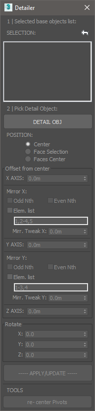
Detailer
Best suited to be used as a complement of the Paneling tool. This utility allows to parametrically place an object over a selection
- Select the Panels (or objects) you want to add the features. The list on top will change dynamically showing the selected objects. Use the <- button to reset the selection.
- Pick a detail (feature) object.
- Offset options:
- XYZ displacement from base object center.
- Mirror: Will mirror objects following the selected rule. note that the indexes correspond to the object’s order in the selection list.
- ODD and EVEN: Mirror odd or even Nth in the list.
- List: type comma separated individual objects numbering or use score symbol to set a range of objects.
- Mirror: Will mirror objects following the selected rule. note that the indexes correspond to the object’s order in the selection list.
- Rotate Details.
Re-center pivots is intended to address situations where the detail object has a displaced pivot from its center, or to correct misplaced pivots in the result.
Map tools and multiMap
Texture coordinates related tools
![]()
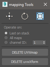
Map tools
Fit, center, reset UVW gizmos (this tolls are only available by default through the UVWmap modifier in the command panel, they where written from scratch ) and delete UVW or UVWxform modifiers in selected objects from a convenient dialog.
By default, Delete UVWmap removes only the last modifier on object’s stack. Use LEFT CLICK to delete all the modifiers in stack. The same applies to Delete UVWXform.
![]()
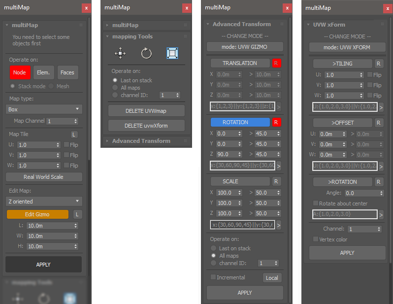
multiMap
Add individual UVW modifiers to a selection of objects, poly elements or faces. Randomize gizmos, transform direct mesh coordinates or add random UVWxform modifiers
![]()
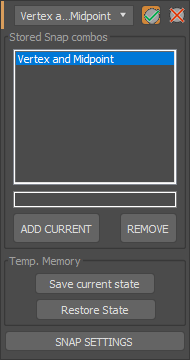
Snaps states
Save current active snaps as a named set and reuse them from the floater dropdown list
![]()
UI reference
Menus
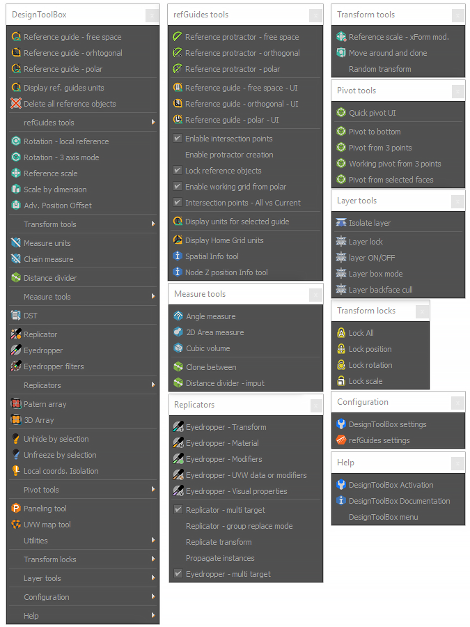
Where to locate the toolbar macros
You can find the tools in the customization dialog under the categories of refGuides, DesignToolBox and the extras in DSTLBX tools
Ribbon Tab
refGuides panel
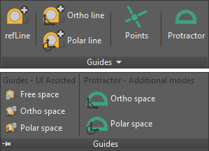
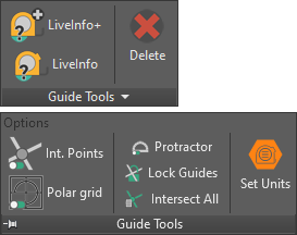
Options not available in toolbars:
- Int. Points / Protractor / Polar Grid toggles
- Units, angles (for protractor & polar tracking) and extension spinners.
- Lock guides after creation toggle.
- Intersect All / Intersect current creation toggle.
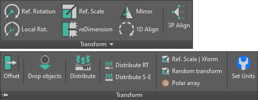
Transform panel
Measure panel
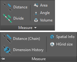
Option not available in toolbars: reference angle for rotation tools angle lock.
Replicator and Eyedropper panel
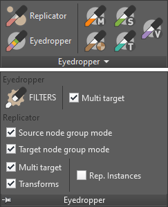
Options available in toolbars as Checkbuttons:
- Replicator
- Replace groups: By default replicator replaces picked objects inside groups and not the entire group.
- Transforms: Keep the original object standard transformations.
- Multi target: On by default, enables the tool to pick more than one destination object.
- Eyedropper
- Multi target: On by default, enables the tool to pick multiple destination objects.
Scene tools panel
General tools panel
Object related tools
Layer tools panel
Extras
![]()
Mesh stamp tool
Use an object to Interactively stamp its shape or cut holes in a mesh.
- Objects must be geometry that can be converted to Editable Poly.
- This tool will collapse the modifier stack.
- Use the UI to pick a base node to operate on
- Choose the operation
- Select a tool object in the scene, and press the start button
- The tool object will be positioned in the base object surface, following the mouse; use right-click to stamp the object shape or left click to end the operation.
- Keep pressed SHIFT and move the mouse to displace the tool towards-away the target surface.
- Keep pressed CTRL and move the mouse towards-away from the tool object to rotate it around its normal.
- Keep pressed CTRL+SHIFT and move the mouse towards-away from the tool object to change its scale.
Photographic composition guides
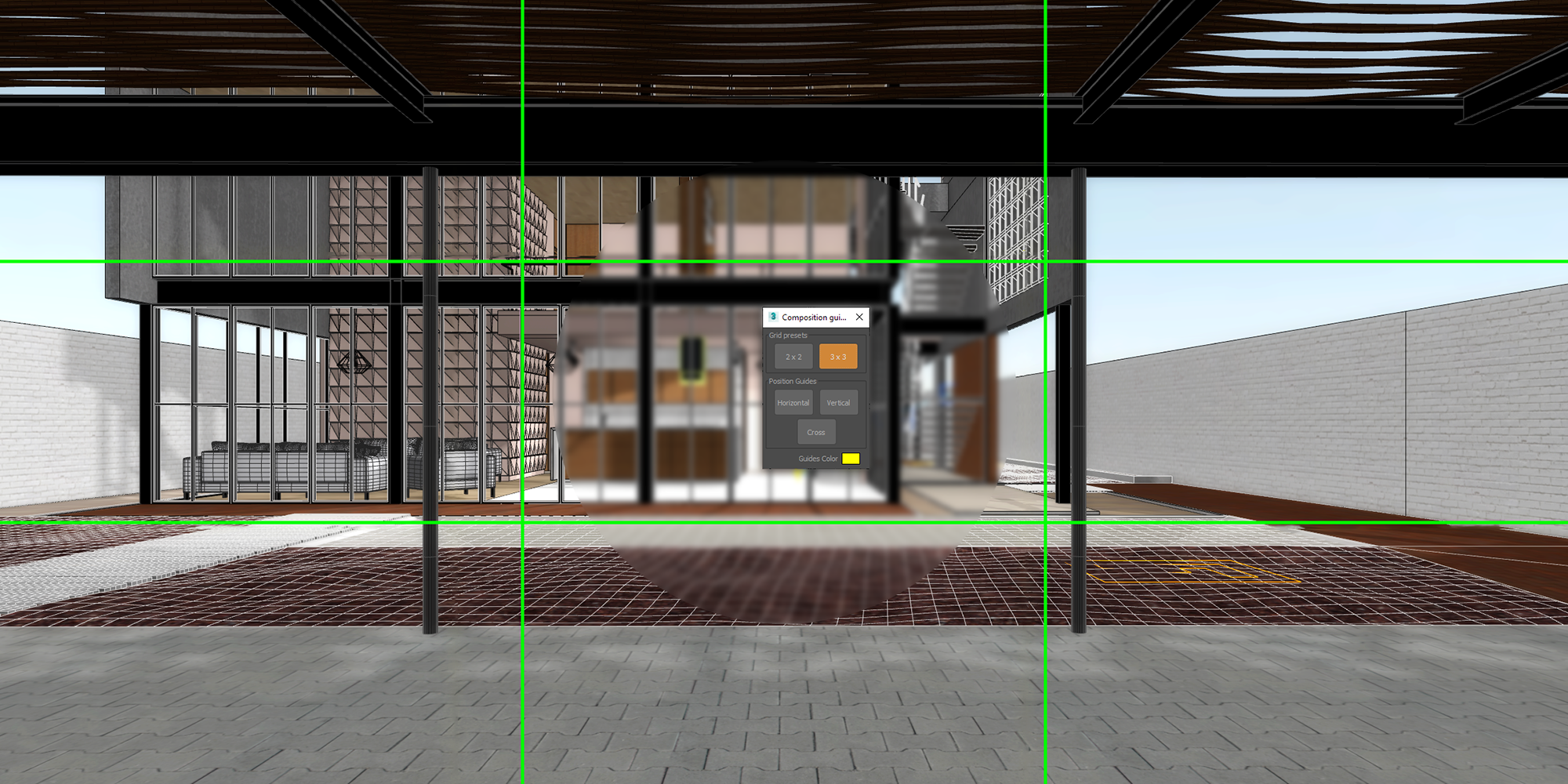
Display an overlay of photographic composition guides in the viewport. This tool is intended to be of aid when composing shots. Easily draw common photographic grids, reference and perspective lines to help compose the perfect shot.
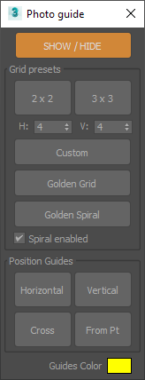
Features
- Quadrants (2x2)
- Rule of thirds (3x3)
- Golden proportions
- Golden ratio rectangles & spiral
- Position a guide in the viewport with the mouse. Possible positions:
- Vertical
- Horizontal
- Cross
- From point: Position multiple Two-point aligned lines from a common base point. Useful to draw perspective lines from a vanishing point or follow the same perspective line.
- You can select the color of the guides.
Tool UI
Install folders
- Main files are installed in 3ds Max’s root directory Scripts (Designtoolbox subfolder) and Plugins folders.
- MacroScripts files are placed in 3ds Max root directory MacroScripts folder.
- Icons are installed in the UI_ln folder in 3ds Max root directory.
- The ribbon extension is language dependent, it will be installed in the corresponding folder for the language selected during installation. I.E. /maxroot/EN_US is the default directory.
- The Plug-in will create some configuration files in the current user folder under the following paths:
- ../UserScripts/DesignToolbox (user information)
- ../en-US/plugcfg (tools saved configuration files)